DESCRIPTION OF THE TYPE OF MEASURING INSTRUMENT Measuring installations "Satellite-Mass Meter NT.1"
Purpose of the measuring instrument
Measuring installations "Sputnik-Massometer NT.1" (hereinafter referred to as installations) are designed to measure the mass and mass flow rate of borehole fluid (crude oil) as part of an oil and gas mixture, the mass and mass flow rate of crude oil excluding water (oil), measurements of the volume and volume flow rate of free petroleum gas, reduced to standard conditions.
Description of the measuring instrument
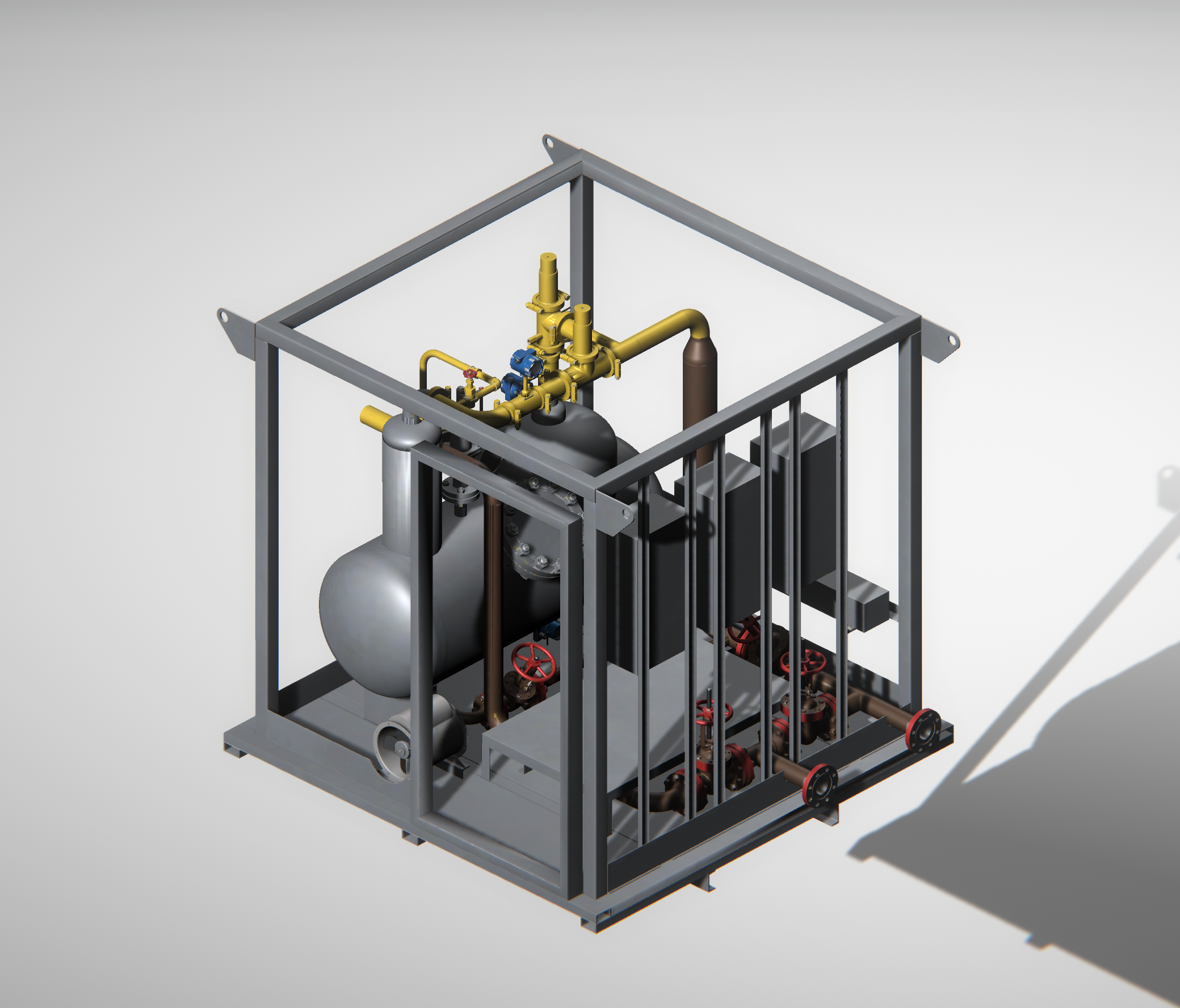
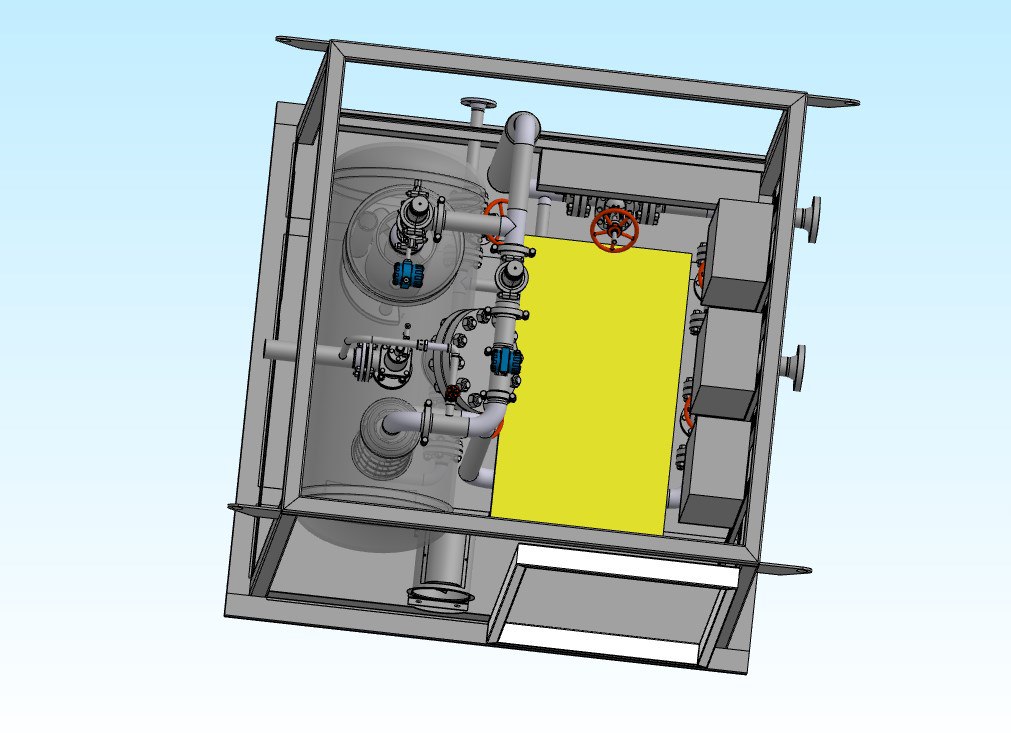
The principle of operation of the units is based on measurements of the mass and mass flow rate of crude oil, mass and mass flow rate of crude oil without taking into account water, volume and volume flow rate of free petroleum gas reduced to standard conditions after separation in the separator.The installations consist of a control and control unit (hereinafter referred to as BKU) and a technological unit (hereinafter referred to as BT).
Installations can be manufactured both in stationary and mobile versions, designed to connect a single well. In the manufacture of installations in the mobile version, the BT unit (a variant of the installations for connecting one well) and the BCU unit are installed in the body of a trailer or car, or on the chassis of a trailer or car.
The BKU includes a power cabinet, a measurement and information processing unit (hereinafter referred to as BIOI). In the embodiment of a stationary installation for connecting one well, the BIOI in an explosion-proof version can be installed in a BT.
The BT, depending on the design, includes measuring instruments (hereinafter referred to as SI): flow meters for mass and mass flow of liquid and gas, pressure, temperature, gas contamination, fire alarm sensors and equipment: protection against unauthorized access, separation tank (hereinafter referred to as EC) or pipe separator (hereinafter referred to as TC) , switching and regulating devices, pipelines with shut-off and control valves.
The BT, depending on the design, includes measuring instruments (hereinafter referred to as SI): flow meters for mass and mass flow of liquid and gas, pressure, temperature, gas contamination, fire alarm and equipment: protection against unauthorized access, separation tank (hereinafter referred to as EC) or pipe separator (further - TC), switching and regulating devices, pipelines with shut-off and control valves.
Depending on the design, configuration of measuring instruments and equipment, the units are available in the following versions:
- version 1 – with a mass liquid flow meter, a flow moisture meter in a liquid line and a mass gas flow meter in a gas line;
- version 2 – with a mass liquid flow meter, without a flow moisture meter in the liquid line and a mass gas flow meter in the gas line;
- version 3 – with a mass liquid flow meter, a flow moisture meter in a liquid line and a volumetric gas flow meter in a gas line;
- version 4 – with a mass liquid flow meter, without a flow moisture meter in the liquid line and a volumetric gas flow meter in the gas line;
- version 5 – with a volumetric liquid flow meter and a flow density meter of liquid in a liquid line and a volumetric gas flow meter in a gas line;
- - version 6 – with a mass flow meter of liquid/gas or with a volumetric flow meter of liquid/gas and a flow density meter of liquid on a common measuring line of liquid/gas;
Installations in different versions measure the mass and mass flow rate of liquid, the mass and mass flow rate of dehydrated oil, the volume and volume flow rate of gas, given to standard conditions in automatic mode, taking into account:
- values of water and oil density introduced into the BIOI program, measured by standardized methods in laboratory conditions;
- corrections for pressure and temperature of the working medium;
- gas content of the working medium;
The list of the main SI, which are completed with the execution of the installations, is given in Table 1. The measuring instruments included in the installation are determined based on the requirements of the questionnaire for the installation or the technical specification of the customer.
Table 1 is a list of the main SI, which are equipped with modifications of
the plant versions.
| Name of the measuring instrument | Registration number in the Federal Information Fund for Ensuring the Uniformity of Measurements |
|---|---|
| Mass flow meters "Micro Motion" | 45115-16 |
| Mass coriolis flowmeters ROTAMASS | 27054-14 |
| Promass X mass flowmeters | 50365-12 |
| Mass flow meters SKAT | 60937-15 |
| Liquid counter mass MASK | 12182-09 |
| SKJ liquid quantity Counters | 14189-13 |
| Liquid quantity counters chamber SKJ | 75644-19 |
| Liquid quantity counters EMIS-MEASURE 300 | 65918-16 |
| Mass flow meter ELMETRO-Flomak | 47266-11 |
| Mass emission meters 260 | 42953-15 |
| OPTIMASS mass flow meters | 50998-12 |
| Mass Fine-Mass flow meters | 70629-18 |
| Flowmeters-counters of mass flow and mass of liquid ERMASS.NT | 70585-18 |
| Flowmeters-counters vortex ERVIP.NT | 60269-15 |
| Vortex flow meters ERVIP.nt.M | 70119-18 |
| Vortex flowmeters IRGA-RV | 55090-13 |
| Vortex flowmeters IRVIS -RS4M | 30206-05 |
| Gas flow sensors DRG.M | 26256-06 |
| SWG vortex gas meters | 13489-13 |
| Universal MICONT-186 controller | 54863-13 |
| Device secondary heat and power controller IM-2300 | 14527-11 |
| UVP-280 calculators | 53503-13 |
| Design and measurement converters TEKON-19 | 61953-15 |
| Moisture meters of crude oil VSN-AT | 42678-09 |
| Moisture meters of crude oil VSN-PEAK | 59365-14 |
| Moisture meters of crude oil VSN-2 | 24604-12 |
| Density meters | 804 47933-11 |
| Liquid and gas quantity measurement systems R-ATMM/D/PIK | 46883-11 |
| Liquid and gas quantity measurement systems R-AT-MM/FS | 50171-12 |
| Liquid and gas quantity measurement systems R-AT-MM | 39821-13 |
| Measuring controllers programmable converters I-7000, I-8000, M-7000 | 20993-06 |
| Controllers based on SCADAPack measuring modules | 16856-08 |
| SCADAPack controllers 32/32P, 314/314E, 330/334E,330E/334E, 350/357, 350E/357E, 312, 313, 337E, 570/575 | 69436-17 |
| Measuring controllers AT-8000 | 42676-09 |
| Measuring-computing and control complexes based on the Logix 1 platform | 42664-09 |
| Measuring controllers R-AT-MM | 43692-10 |
| Measuring controllers R-AT-MM | 61017-15 |
| Controllers of the mechanized bush of KMKS wells | 50210-12 |
| Direct Logic measuring controllers DL05, DL06, DL105, DL205, DL405 | 17444-11 |
| Programmable controllers DirectLOGIR, MTCCLICK, Productivity, Productivity3000, Protos X, Trminator | 65466-16 |
| Logic controllers programmable PLC 160 | 48599-11 |
| SIMATIC S7-1200 programmable controllers | 63339-16 |
| Measurement modules of SIMATIC S7-1500 programmable controllers | 60314-15 |
| SIMATIC S7-200 programmable controllers | 15771-10 |
| Measuring and computing modules MSXX | 76108-19 |
| Software control devices "TREI-5B" | 31404-08 |
| Modular control systems B&R X20 | 57232-14 |
| Software and technical complex "Mega" | 48782-11 |
| Infoluk multifunctional software and hardware complex | 56369-14 |
| Automation and telemechanics complexes multifunctional software and hardware "Sphere-1" | 8647-14 |
| Multifunctional Software and hardware complexes "Orbita" | 53630-13 |
| Pressure measuring transducers, with a measuring range of 0-25.0 MPa and the limits of the permissible reduced error of no more than ± 0.5%, analog current output signal; | |
| Temperature measuring transducers, with a measuring range of 0-100 °C and limits of permissible absolute error of no more than ± 0.5 ° C, analog current output signal; | |
| Thermometers showing with measurement limits 0-100 ° C, absolute error ± 0.5 °C | |
| Pressure gauges showing with measurement limits of 0-6.0 MPa, cl.t. not less than 1.5 |
Factory number indicated on the technological block BT IU.
software< / b> < / p>
software (hereinafter referred to as) for installation consists of software-technical complex "mega" or devices processing information measuring system R-at-MM, комплекса многофункционального программно-технического «Инфолук», МПТК «Орбита», Modular Control System B & R X20, measuring and computing modules MCCxx.
level of protection software " high "according to PR 50.2.077-2014" GSI. Испытания средств измерений в целях утверждения типа. Проверка защиты программного обеспечения». Примененные специальные средства защиты в достаточной мере исключают возможность несанкционированной модификации, обновления (загрузки), удаления и иных преднамеренных изменений метрологически значимой части программного обеспечения и измеренных (вычисленных) данных. ПО на метрологические характеристики установок влияние не оказывает.identification data software (further - on) installation в таблице 2.
Table 2 - software identification data
< / p>
| identification data< / th> | meaning | |||||||||||||||||||||||||||||||||||||||||||||||||||||||||||||||||||||||||||||||||||||||
|---|---|---|---|---|---|---|---|---|---|---|---|---|---|---|---|---|---|---|---|---|---|---|---|---|---|---|---|---|---|---|---|---|---|---|---|---|---|---|---|---|---|---|---|---|---|---|---|---|---|---|---|---|---|---|---|---|---|---|---|---|---|---|---|---|---|---|---|---|---|---|---|---|---|---|---|---|---|---|---|---|---|---|---|---|---|---|---|---|
| PTC "Mega" | R-at-MM | PTK Infolook.Cnfwbjyfhys | ||||||||||||||||||||||||||||||||||||||||||||||||||||||||||||||||||||||||||||||||||||||
| rotor | < th>Mega ORS server < / tr> < / tr> < / tr>||||||||||||||||||||||||||||||||||||||||||||||||||||||||||||||||||||||||||||||||||||||||
| identification of new name < / td> | test cycle machine "rotor" < / td> < td>Mega OPCDA Server | < TD>DebitCalc < TD > Infolook.Polling < / tr>|||||||||||||||||||||||||||||||||||||||||||||||||||||||||||||||||||||||||||||||||||||||
| number of versions (identification number) < /td> | 10HH.HS Borka HHH* | 10X.X.X.XXX * | VO.1 | 1.00.5036.24320 | < / tr>||||||||||||||||||||||||||||||||||||||||||||||||||||||||||||||||||||||||||||||||||||
| digital identifier for | 790413C09D058 BD0A7E70DB8 B8C65B73 | 23C6EA0409293 54V928D66FC F66D40D4 | 3a0442256a3a be0f64a7c4e92 7160bd3 |
41C7972BB766F B745D36B393A 88B5800 < / tr> | ||||||||||||||||||||||||||||||||||||||||||||||||||||||||||||||||||||||||||||||||||||
| identification data< / th> | meaning | |||
|---|---|---|---|---|
| PTK "orbit" | modular Control System B&R X20 < th>modules measuring-calculating MCCxx < / tr> < / th> < / tr>||||
| identification by | arm fixing system "Orbita" < / td> | arm survey system "Orbita" < / td> | B & R Automation Studio | < td>MCCxx_v7.bin< / td> < / tr>|
| number of versions (identification number) < /td> | 2.5.1.3.7 | 2.5.1.85 | not lower than V2. 6< / td> | 7/00 | < / tr>
| Digital ID by | C6C0IASS65C91 1A44C8D94ECA 91F0C61 |
5C9735EC7700 9F9828501862 BB2F9A8D |
Version Number | - |
| Other identification data - algorithm for calculating the digital identifier of the software | md5 | md5 | Not used | Not used |
Metrological and technical characteristics
The metrological and basic technical characteristics of the installations are given in Tables 3 and 4.
Table 3 – Metrological characteristics
| Name of the characteristic | Value |
|---|---|
| Measurement range of average daily mass consumption of crude oil, depending on the version of the units, t/day: -for stationary installations- for mobile installations | up to 3000 to 1500 |
| Measurement range of the average daily volume flow of associated petroleum gas, reduced to standard conditions, depending on the version of the units, m3/day: - for stationary installations - for mobile installations | up to 1000 000 up to 500 000 |
| Limits of permissible relative basic error of measurements of mass and mass flow of crude oil, | % ±2.5 |
| Limits of permissible relative basic error of measurements of mass and mass flow of crude oil excluding water at water content (in volume fractions), %: - from 0 to 70% - from 70 to 95% - over 95% to 98 % - over 98 % | ±6.0 ±15.0 ± 30.0 is not normalized |
| The limits of the permissible relative basic error of measurements of the volume and volume flow of free petroleum gas, reduced to standard conditions, % | ±5 |
Table 4 – Main technical characteristics
| Name of the characteristic | Parameters |
|---|---|
| Working environment | crude oil |
| Working environment temperature, | °From 5 to 60 |
| Viscosity of the liquid, mm2/s, | no more than 150 |
| Working medium pressure, MPa (kgf/cm2), | no more than 25 (250) |
| Density of dehydrated oil, | kg/m3 from 700 to 900 |
| Reservoir water density, | kg/m3 from 1000 to 1200 |
| Range of values of the volume fraction of reservoir water in the liquid, | % from 0 to 99.9 |
| Paraffin content, volume fraction, %, max: | 7 |
| The content of mechanical impurities, volume fraction, (mass fraction) , %, (mg/l), no more: | 0,05 (2500) |
| Hydrogen sulfide content, volume fractions, %, (mass fractions), (mg/l), no more: | 18 (277,056) |
| Carbon dioxide content, mass fractions, mg/l, not more than: | 1400 |
| Gas factor, nm3/t, depending on the capacity of the installations | 150; 200; 300; 1500; 3000 |
| Current type | variable |
| Voltage, V | 380/220 |
| Mains supply voltage deviation, % | from - 15 to + 10 |
| AC frequency, Hz | 50±1 |
| Power consumption, kVA, no more than | 20 |
| Communication channels: - RS485 - RS 232S/485 | Modbus protocol (master) Modbus protocol (subordinate) |
| Number of connected wells - for stationary installations - for mobile installations | from 1 to 14 1 |
| Diameter of connecting pipelines, mm, not less than | 50 |
| Ambient air temperature | from - 45 °C (Y1) and -60 °C (UHL1) up to +40 °C |
| Relative humidity, %, max | 80 |
| Average time to failure for measurement and parameter determination functions, h, at least | 3500 |
| Average recovery time of the functional state of the equipment, h, no more than | 8 |
| Service life, years | 20 |